Network Security - Part 3: Network Firewalls
A lot of people in the security industry have been talking about the de-perimeterisation of the network for a few years now. Even though attention has shifted away from prevention technologies and companies are investing more time, money, and effort into detection and response, the truth is that protecting the perimeter from external attacks is still relevant today. You might not be able to block every malicious packet from entering your network but if you can slow the attacker down you’ll have more time to detect them and respond to the attack before they get access to a critical system.
Network firewalls are the first line of defense against external attackers, and as such, they should be configured properly. This blog post will describe how to configure pfSense as a network firewall and create a basic set of rules for our environment.
Aliases
Aliases allow you to group IPs, networks and ports together. This will help in keeping your firewall rules clean and easy to understand. The lab that we built on Part 1 of this series is pretty small but imagine the level of complexity involved in managing a firewall for a big enterprise environment.
pfSense comes with a set of pre-configured aliases:
| Alias | Value |
|---|---|
| WAN net | 192.168.15.0/24 |
| WAN address | 192.168.15.1 |
| LAN net | 172.16.1.0/24 |
| LAN address | 172.16.1.1 |
| OPT1 net | 176.16.2.0/24 |
| OPT1 address | 172.16.2.1 |
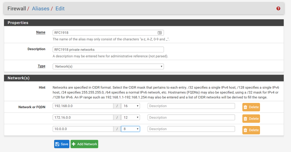
We will start by creating an alias for every private network as defined in RFC1918. Log in to the pfSense admin console and go to Firewall > Aliases to add a new network alias:
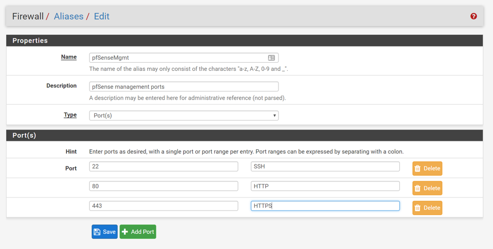
Next, create a port alias that includes all the pfSense management ports (SSH, HTTP, and HTTPS):
WAN Interface
Let’s create rules for our WAN interface. Remember that WAN (Wide-Area Network) really means “The Internet” here. We will assume for now that we want to block all inbound traffic into our internal network. This method is sometimes called “Default Deny” or “Explicit Allow”.
Go to Firewall > Rules > WAN to add a new rule:
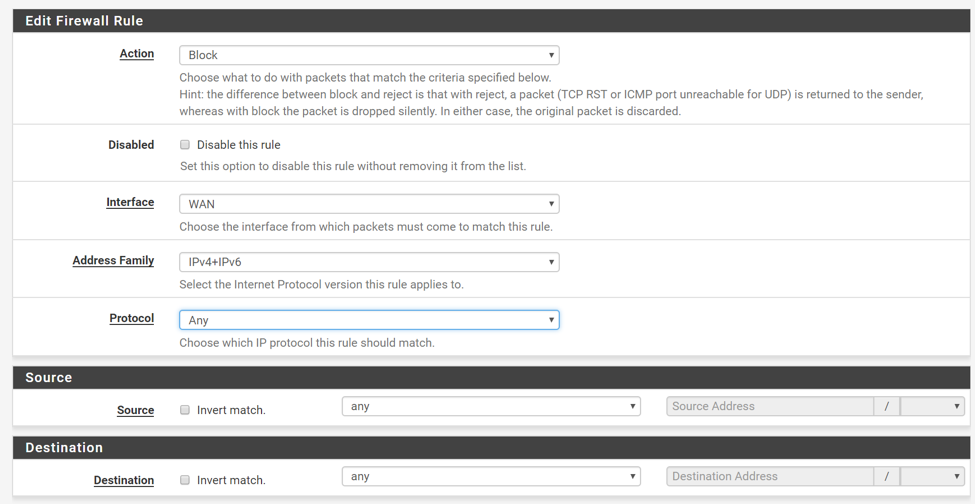
Let’s break the rule down so that it makes more sense:
- Action : determines whether the packet should be “Allowed” to enter the interface or not. Packets can be “Blocked” (drop silently) or “Rejected” (drop the packet and return an error message to the sender). I suggest using “Block” when possible to avoid giving the attacker information that could be used to map out your network using a tool like nmap.
- Interface : interface from which packets must come from. In this case, all packet must come from the WAN interface (Internet).
- Address Family : this is the IP version which can be IPv4, IPv6 or both.
- Protocol : this is the IP protocol (TCP, UDP, ICMP, etc…).
- Source : IP or IP range (subnet) of the sender.
- Destination : IP or IP range of the receiver.
More information about how pfSense performs rule matching can be found in the official wiki. However, a couple of points are worth mentioning here:
- Firewall rules process traffic in the inbound direction. That is, rules defined on the WAN interface only process traffic coming from the WAN interface into the LAN, or OPT networks.
- Rules are processed from the top down, stopping at the first match. Be extremely careful how you order your rules. Adding an “Allow Any Any” rule at the top, will effectively bypass any other rule you might have created.
- When no firewall rules match the incoming request, traffic is denied. This means that if there are not rules defined, all incoming packets will be denied. Another way to think about this is to assume that at the end of the rule set there is always an implicit deny any rule.
Internal Interface
Now that we know how firewall rules work, creating a rule set for our internal interface should be pretty easy.
Currently, our internal interface is not very secure. This is because pfSense added a default “Allow OPT1 to any” rule when the interface was first configured. If you don’t believe me, log in to the nsClient VM and connect it to the internal network:
$ sudo ifdown enp0s8 $ sudo ifup enp0s3
Open Firefox and verify that you can reach the pfSense management portal (https://172.16.2.1):
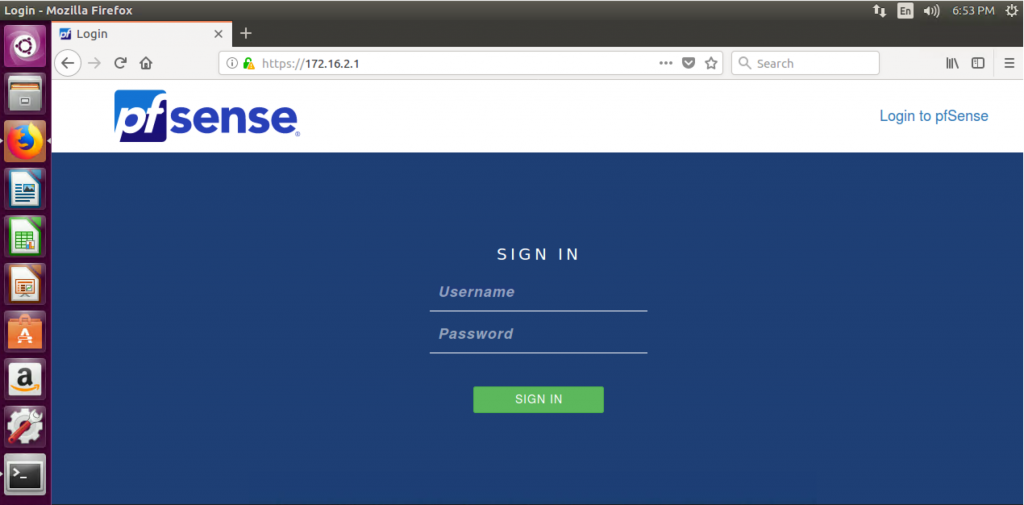
Do we really want to allow access to our router from any device connected to the internal network? Probably not. That’s why we created a separate management network in the first place!
We’ll fix this by creating the following rules:
- DNS access : allow TCP/UDP from OTP1 subnet to OTP1 address port 53.
- NTP access : allow UDP from OTP1 subnet to OTP1 address port 123 for NTP.
- ICMP access : allow ICMP from OTP1 subnet to OTP1 address to ping the gateway.
- Reject any from OTP1 subnet to RFC1918. This will prevent OTP1 from accessing any other private networks.
- Allow any from OTP1 subnet to any so that devices can access the Internet (*see comment below).
Your rule set should look similar to this:
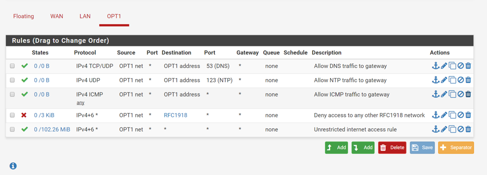
Notice the use of the RFC1918 alias, as well as OPT1 net (172.16.2.0/24) and OPT1 address (172.16.2.1).
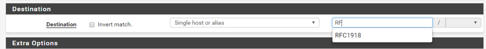
To select the RFC1918 alias as the destination, select “Single host or alias” and start typing the alias name until you see the drop down list:
With these rules in place you won’t be able to connect to the pfSense management portal from the client VM anymore. However, you should still be able to connect to the internet.
*Note: In this case, we decided to use an “Implicit Allow” approach to make sure all clients can still connect to the internet without any restrictions. In a production environment you can (and should) lock it down by explicitly allowing access to only certain services such as HTTP/HTTPS, SMTP, POP3, IMAP, etc…The pfSense documentation has a nice article about this.
Management Interface
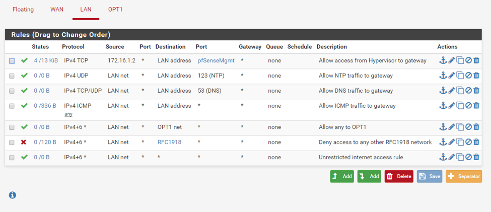
Similarly, we need to create some firewall rules for our management interface:
- Allow access from hypervisor host (172.16.1.2) to pfSense management ports. On the “Destination Port Range” select “(other)” and enter “pfSenseMgmt” as the value.
- Allow TCP/UDP from LAN subnet to LAN Address port 53 for DNS.
- Allow UDP from LAN subnet to LAN address port 123 for NTP.
- Allow ICMP from LAN subnet to LAN address to ping the firewall from the LAN.
- Allow any from LAN to OPT1.
- Reject any from LAN subnet to RFC1918.
- Allow any from LAN subnet to any so that devices can access the Internet.
These rules are pretty similar to the ones we created in the previous section with the exception of #1 and #5. We need #1 to connect to the pfSense management interface(s) from the hypervisor host, and #5 to access any host on the OPT1 network.
You should end up with the following rule set:
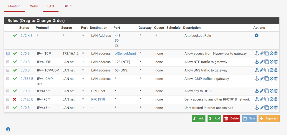
You might be wondering who created the “Anti-Lockout Rule” that shows up first on the list. This rule was created automatically by pfSense and it prevents firewall rules from being configured in a way that will lock the user out of the web interface. Notice that rule #1 on our list effectively replaces the anti-lockout rule and even goes a little bit further by allowing connections only from the hypervisor host. Clicking on the wheel icon should take you to System > Advanced where you can disable the anti-lockout rule:
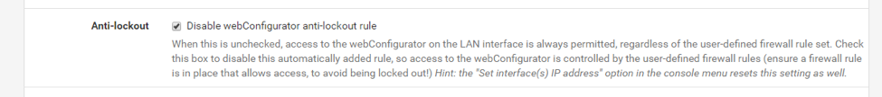
Save your changes and verify that the rule is now gone:
Port Forwarding
Now that we have locked down our environment the question becomes, what if we want to expose an internal resource, such as our web server, to the internet (WAN network)? The answer to this problem is port forwarding.
Log in to the pfSense portal and got to Firewall > NAT > Port Forward to create a new rule:
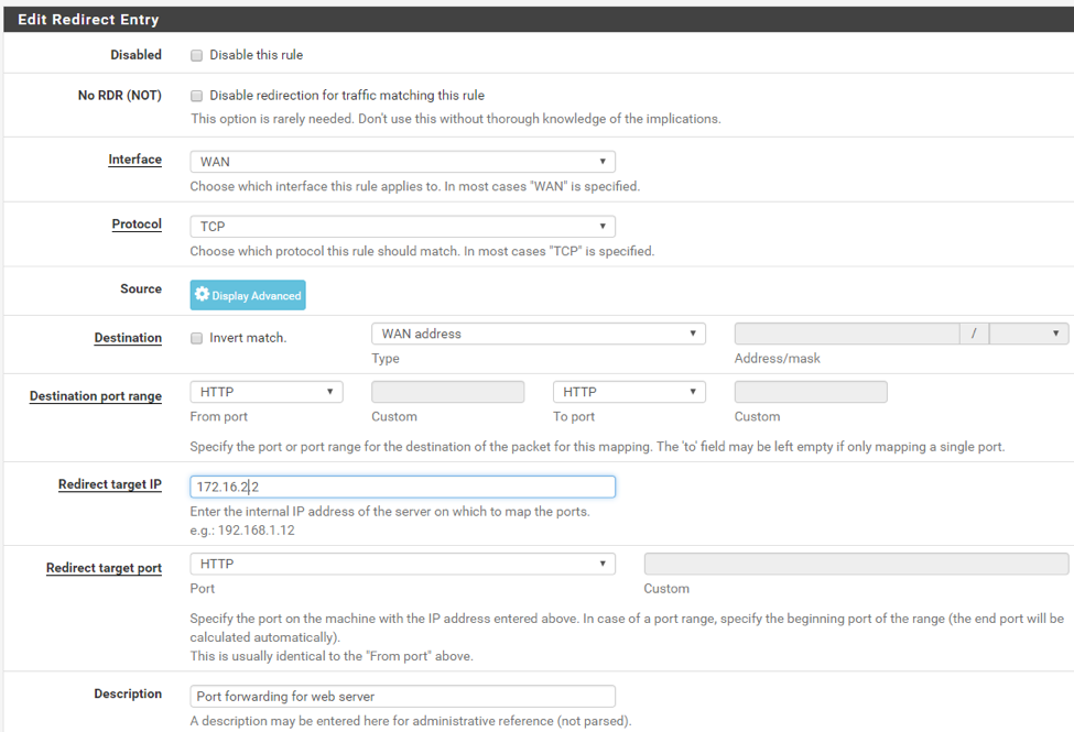
Essentially, this rule tells the router to forward incoming HTTP requests with destination “WAN address” (http://192.168.15.4:80) to our internal web server (http://172.16.2.2:80).
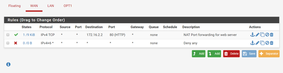
When adding a port forward rule, a firewall rule must also be added to allow traffic in to the internal IP address designated by the port forward (172.16.2.2). If you selected the default “File rule association” value:
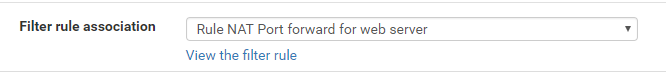
pfSense will have created the firewall rule automatically for you. Make sure the rule shows up above the “Deny any” rule (you might have to swap the rules manually):
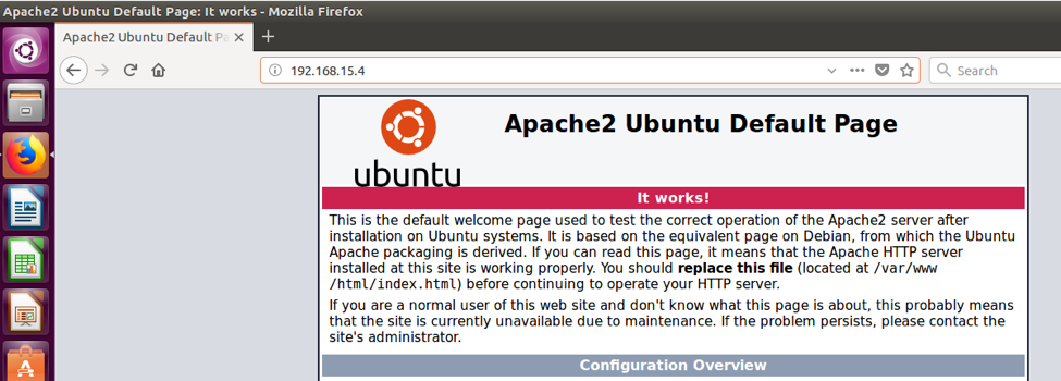
Log in to the nslClient VM and and connect it to the external network:
$ sudo ifdown enp0s3 $ sudo ifup enp0s8
Then, verify that you can now access http://192.168.15.4:80:
Logging
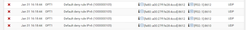
By default, pfSense will log connections that were blocked by the implicit deny rule. Go to Status > System Logs > Firewall to see these logs:
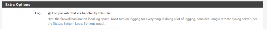
You can enable logging for each custom rule individually by selecting the following check box in the rule definition:
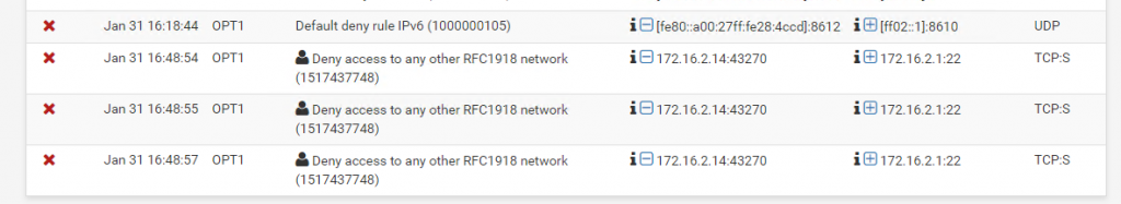
After saving your changes you’ll start seeing messages like these ones:
Closing Thoughts
Even though this configuration might not be the most secure, I hope it serves to illustrate the fact that firewalls play a critical role in securing your network. That being said, firewalls are not the solution to all our security problems. In fact, there is no magic bullet to security. An that’s the reason why we will follow a defense in depth approach and explore how to add additional security layers to our environment in future posts.